The Oramics Machine
Oram’s ‘drawn sound’ synthesis and sequencing system
The Oramics Machine enabled Oram to synthesise and sequence sound by painting lines and other marks on glass and film strip. Oram invented it as a new means of musical expression, one that enabled her to finely control and vary sounds in ways that went beyond the capabilities of audio tape. The story of Oramics is told here by composer and instrument builder Tom Richards. Tom also outlines his own work building a Mini-Oramics machine from Oram’s original notes and drawings.
The Oramics Machine is an electro-mechanical and opto-electronic musical interface conceived, co-designed and commissioned by Daphne Oram between 1962 and 1969. It used optical scanning technologies to read and interpret hand-drawn waveforms (timbres) and sequences of control information for musical pitch and dynamics. It can be seen as a forerunner of MIDI sequencing and the digital audio workstation (DAW). The Oramics Machine never went into commercial production – it remained as an evolving prototype, with Oram developing several different methods for reading and interpreting the drawn input material over the Machine’s lifetime. The Oramics Machine is now held in the permanent collection of the Science Museum.

In the mid-1950s, while Daphne Oram was working as a studio manager at the BBC, she started to formulate ideas for a new musical interface. Oram’s particular focus was on techniques which would allow the composer a more direct and visual method for electronic composition. The manipulation of audio material using ¼-inch tape (known as musique concrète) was the standard method for electronic composition at the time, and this had two major technical disadvantages. Firstly, pitch and tempo were inconveniently and inextricably linked – the higher the tempo, the higher the pitch for any given recording. Secondly, there was no means to see what sounds were on the tape at any given point.
Oram’s initial designs for transferring graphic notations directly into sound and control signals were electromechanical in nature. She planned to use circular motion to generate musical pitches; either by modulating a light source with adjacent photocell, or similarly modulating a drum of electromagnetic tape with a ‘drawn’ waveform produced by using a slide potentiometer.

An independent studio – and a working prototype
As the BBC Radiophonic workshop was formed in 1958, with Daphne Oram and Desmond Briscoe at the helm, it became apparent to Oram that the BBC would not support her drawn sound research. Oram also was aggrieved about the lack of credit she received for her electronic sound works, and so in 1959 she decided to leave the BBC and form her own electronic music studio in order to pursue her research independently.
In 1962 Oram managed to obtain a grant of £3500 from the Calouste Gulbenkian Foundation (about £50000 in today’s money), to try and build a prototype drawn sound interface over a three-year period. Oram’s engineer brother John Oram built the mechanical transport mechanism while GPO-trained electronics engineer Fred Wood assisted Oram with the electronics.
Initially progress was slow, especially as Oram was taking on a lot of other work in film and theatre soundtracks, live performances and lecture tours. By 1964 it became apparent that extra help would be needed, and Oram employed another electronics engineer, Graham Wrench, who would have a big impact on the project.
When Wrench joined the project, the mechanical transport for the machine was mostly complete and it had already been decided that synchronised strips of blank 35mm movie film would be the format for drawn control parameters. It had also been decided that repetitively scanning drawn wave patterns on glass slides would create the different electronic timbres for the machine. Wrench was able to create improved electronic circuits to take these concepts into reality, although what exactly the control parameters would be was still very much in flux.
By the summer of 1966, with the help of a small additional grant from the Gulbenkian Foundation, Oram was able to report that she had a working prototype. At this point the machine worked as follows:
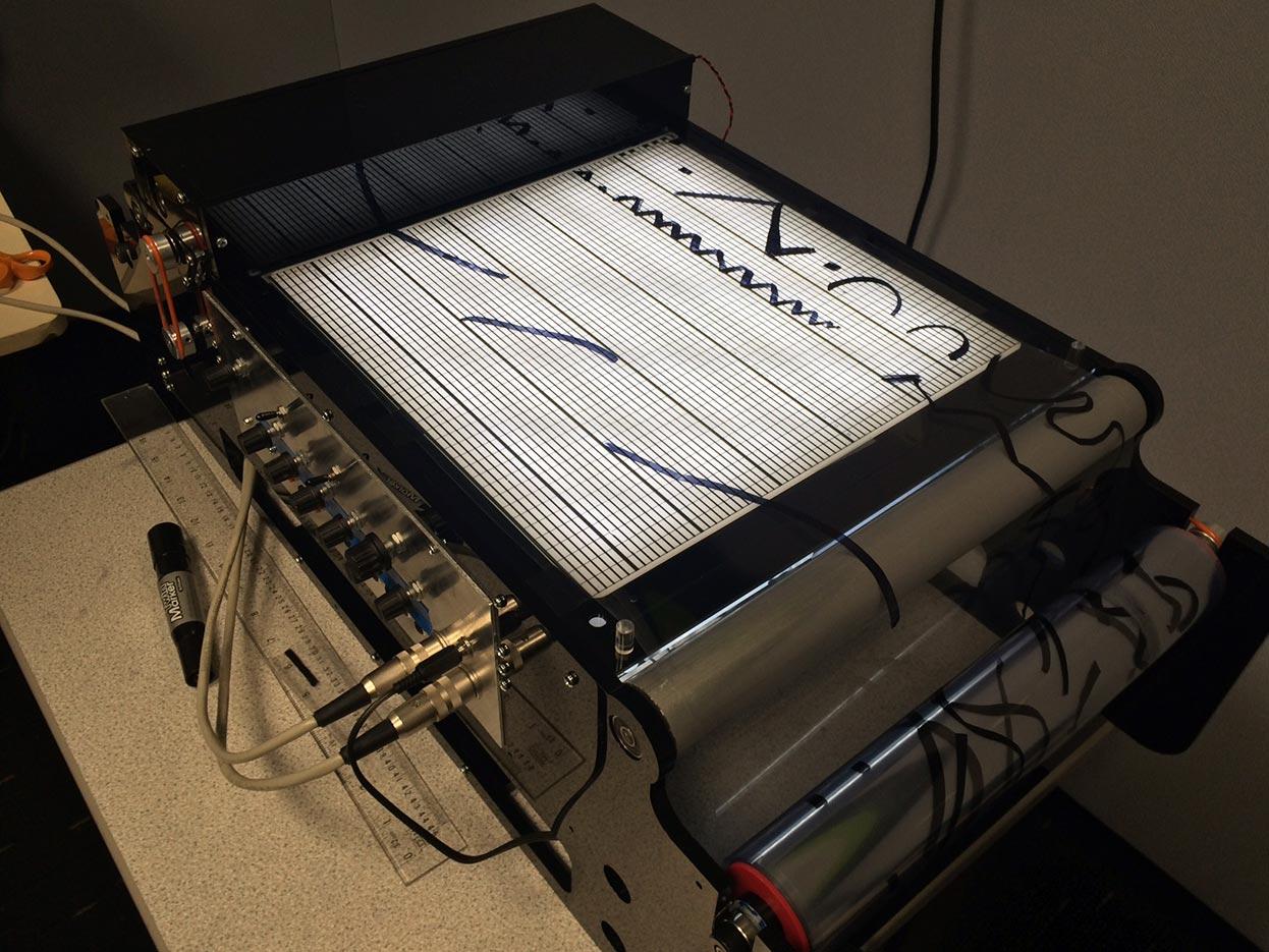
First the composer would draw a set of four wave patterns on glass slides and insert these into the scanning apparatus.
Then a set of codified pitch information would be drawn across three strips of 35mm film (across a total of 12 LDR light sensors). Then as the film moved, the light sensors activated small relays (electronic switches) which in turn controlled a network of resistors and capacitors which eventually controlled the pitch of a master sawtooth oscillator. Oram referred to these pitch codes as neumes. These circuits were based on digital flip-flops (memory cells) and as such, it was a very early digitally controlled oscillator, for which Oram was granted both US and UK patents.
This sawtooth signal then became the time-base signal for the wave-scanners, which worked like oscilloscopes in reverse. The signal repetitively drove bright dots across the X axes of four cathode ray tubes at the frequencies prescribed by the neumes. Then a feedback circuit with another type of light sensor (called a photomultiplier) forced the dots to follow the drawn patterns up and down. The four different timbres were then derived from the Y axes of the cathode ray tubes, outputting electronic waveforms analogous to those drawn by the composer.
Having set the melody and approximate timings, the composer would then draw out the dynamics of the piece. Using a further four strips of 35mm film, the composer was able to specify the volume over time of all four different timbres, using one strip of film per timbre – literally drawing volume graphs. This was important as it meant that the composer could automatically blend and shape the timbre within each musical note – an extremely advanced capability at the time.
The composer was then given two more analogue controls, each with their own dedicated film strip. Pitch vibrato allowed a subtle bending of the pitch, and another volume channel applied different amounts of reverberation to the overall timbre mix. Oram used a separate room with a speaker and microphone to record a natural acoustic reverb.


Oram recorded some amazing sounds and musical progressions with the machine, but she also had a lot of trouble keeping it running reliably and keeping it in tune, as documented in her technical logbooks of the period 1966–1973. This was compounded by the fact that, for reasons that it is impossible to confirm, in the summer of 1966 she fired Graham Wrench from the project, and also cut ties with her brother John over financial issues.
Between 1966 and 1972 Oram changed the way the tuning worked several times, and she was also, after much frustration, forced to give up on Wrench’s analogue control system. The analogue controls initially worked similarly to the wave scanners, with the lines on the films forcing a CRT spot to follow them up and down; the spot position then became the control signal – each analogue channel had a tiny one-inch CRT built into it. This meant that the composer could draw simple lines rather than ‘filled in’ graphs. However, Oram was unable to keep this system working and eventually had to resort to a clunkier ‘filled in’ graph system, where the analogue control drawings had to be completely opaque and the underside of the graphs had to be laboriously filled in with photographic ink or black electrical tape. This meant that she could use much simpler LDR-based sensor circuits to create the necessary control signals.
In the early 1970s, Oram became increasingly frustrated with the Oramics Machine’s technical issues. As electronics technology had moved from valves to transistors to tiny integrated circuits (microchips), Oram put her energies into trying to make a new version of her machine with the assistance of electronics engineers Norman Gaythorpe and John Emmett. She dubbed this new IC-based version ‘Mini Oramics’. Unfortunately, she did not complete it, and in the early 1980s she moved her focus again, this time towards creating a software version of Oramics.
Oramics was a remarkably sophisticated interface for the time in which it was developed, and it is striking in its similarity to the linear time-line based sequencing and editing techniques musicians and engineers use today. It is fair to say that it was at least as sophisticated as some of the well-funded state and university-run electronic music facilities of the time, despite its eccentric appearance.
Bird of Parallax
Perhaps the best example of the Oramics Machine sound is the opening refrain from Oram’s Bird of Parallax. This was composed by Oram in 1972 using sounds from the Oramics Machine as well as concrète tape montage. The piece was written for Xallaparallax, a ballet performed at the Edinburgh Festival.
Mini-Oramics Machine – realised in 2016
In 2016 PhD researcher (and current Oram trustee) Tom Richards managed to create a working version of Mini Oramics, which has now been used by a number of composers, researchers and musicians in the UK and beyond.